 |

|
Magna Tips & Tricks • How to clean and shim/jet your carbs. How to Clean your Carbs. as well as install Jets and Shims OK several have asked if I can do a write up on how to clean the carbs on a Magna. This will be an exact reference to the non California model '94-'03 Magna's but a lot will hold true to the previous generations as well but they will be different. Cali models have many many more hoses, LoL, but basically the same. I have done over 25 of these on the '94-'03 Magna's and it cures the midrange issues as well as the deceleration popping. If you are running aftermarket exhaust and K&N air filter then I would also
suggest the Dave Dodge main jets (105s are what he sells and work great!!!)
I DO NOT recommend the Dyno Jet kit either, as they have you drill the vacuum
slides, they are expensive. Dave's setup is a simple install and no part First make sure you have a good clean place to work, assemble your tools with a good setup metric socket set, wrenches, screwdrivers, and basics. A tip when removing bolts and screws: If you are able, put any removed bolts and screws etc. back into their homes. If you can't, I recommend a multi-compartmented plastic tray for those loose items. (I generally use all the compartments and keep my loose fasteners separated by their various placements) This will assist you in putting the correct screw or bolt or whatever back to its proper home once re-assembly is started. An added bonus is that you are less likely to lose anything during teardown and assembly. Pull the seat by removing the 12mm bolts. Tip: Once the seat is removed I place a shop towel over the battery box area to keep from inadvertently shorting the battery if I place a tool on it. Next turn off your fuel (it would be a good idea to have a near empty tank) at the petcock. With a 6mm Allen wrench; remove the bolt holding the tank, lift up rear of the tank to remove the fuel supply line. Place a shop towel under the petcock to catch the little bit of fuel that will drain from the hose. Take a big flat blade screwdriver to help with "breaking loose" the hose then gently twist and pull. Remove the shop towel that now has fuel on it, take it out of the work area so you wont have to smell it for the rest of the job. Next you must remove a small 3.5mm vent hose located in the middle of the tank bottom, gently twist and pull, it will come off. Now remove the tank and place in a safe area. Tip: Take some masking tape and place around the end of the small vent tube you just disconnected so that you will remember to reconnect it when re-installing the tank, I see this happen all the time. Next you will need to remove the air filter housing and snorkel. Tip: The screws running around the housing lid are soft, make sure you use a good # 2 Phillip's and get good purchase so you don't strip the head. The lid has 9 screws holding it to the the filter housing. It is a tight fit but the lid and housing will slide out to the left side of the bike with patience. Be careful not to force it as the trumpets for the carbs are soft material that can bend and distort easily. You may have to turn the housing counter clockwise a little to get it out. Patience is the key here - it will come out just don't force it. The air filter base has 3 Phillip's head screws holding it in place. They will usually not come all the way out of the housing so don't worry it is a design feature so you wont accidentally drop them down a carb. The brackets on each side bolt to the base with 10mm bolts. You will also need to remove the plastic chrome faux air cleaner covers, they have a 8mm bolt in the bottom and 2 tension tab/grommets holding them in place. On the left side of the bike it's necessary to remove the entire bracket to gain access to the throttle cable mount. There will be a hose you need to remove along with the choke pull handle, simply slide the idle adjustment knob out of its bail. The right side bracket does not need to be removed, just the bolt at the top holding the air cleaner base in place. There is also a vacuum hose on the rear of the housing base that needs to be removed. Again, patience in removing the air filter base over the trumpets. Now the top of the carbs are exposed, visually check to see if there is any gross amounts of dirt and or varnish. Remove the 2 Phillip's screws that hold the throttle cable adjustment mount to the carb body. Gently work the cables loose from the throttle plate wheel, mark each cable if necessary as you remove to make sure you get them re-installed correctly. The auto fuel shut off diaphragm has 2 hoses coming off one with a "T". Rremove this from the diaphragm. Usually needs gently persuasion with a flat blade screwdriver to release. Next you will need to loosen the rubber boots (several turns you want them loose quite a bit) at the carbs don't loosen the bottom at the head intakes. Your are ready to pull the carbs off, but they are in the rubber boots pretty snug. I use 2 small pry bars or very large flat blade screwdrivers wrapped with a shop towel to gently, I say gently break them loose. Make sure you do not pry on them as you are working on a prt that can be broken easily. Patience again is the key. You will see or hear them release, work side to side little bit at a time to make sure you do not damage anything. Once the carbs are released from the boots, you will need to take the choke cable out from under the water pipe. Now you can take the entire carb bank to the bench to work on after you drain the fuel from the bowls. Be careful the bowl screws are soft. Flip the carbs upside down so the bowls are facing up. With an 8mm wrench (5/16's also works) carefully loosen the carb bowls. Once loose enough you can use a # 2 Phillip's screwdriver. Working one bowl as at a time remove the bowl, clean the bowl with some spray carb cleaner and a old toothbrush, wipe dry with a shop towel. You will see the floats, main jet, and the slow jet. Refer to the manual so you know which is the slow jet. Remove it with a flat blade screwdriver. It is brass and very easily damaged so be very careful and patient with them. Once removed; use compressed air to blow through the orifice, hold to the light to see the light shine through the orifice. If you can see the light then it is fine re-install, if not then you need to clean it out again with carb cleaner until it's no longer obstructed. Re-install the bowl and go to the next carb, working one carb at a time. If you plan to install main jets for your aftermarket exhaust then do it now, I recommend the Dave Dodge jet kit. It is the easiest to do and works great, www.drp123.com. Go the contact page and call or email him. The Jet and Shim kit will have great instructions and a tool as well as the jets and shims. The tool is what you will use to adjust the pilot screw. When adjusting the pilot screw I recommend removing it; being careful not to lose the spring, and cleaning it with carb cleaner, then re-install. Tighten down to a light seat (remember it is brass and will easily damage). Once at the light seat back out 2 3/4 turns for completely stock setup. 2 7/8 turns for modified stock mufflers, 3 turns for modified stock mufflers and K&N air filter and 3 1/4 turns for aftermarket exhaust and K&N filter. If installing shims which I highly recommend no matter what, then remove the 3 screws holding the black plastic cover on (be very careful that you do not strip these screws as they are very soft) (This is a great time to replace these soft easily stripped Phillip's screws with good quality Allen head cap screws 4mm x 16 mm long, you will need 3 per carb for a total of 12. Remember the cover is plastic, do not want to break it by over tightening.) Remove the diaphragm spring and diaphragm/vacuum piston containing the jet needle being very careful not to tear the diaphragm. Remove the jet needle holder from the piston by screwing one of the cover screws in the holder, gently pull the holder. Carefully remove the jet needle and the 1 factory installed shim. Add the Dave Dodge shim in addition to the factory installed shim, I have always just added the additional shim on top of the factory shim. Re-install the jet needle in the vacuum piston and replace the holder, make sure you fully seat the holder into the piston, it has an O-ring and needs to be fully seated. You are now ready to re-install the jet needle vacuum piston assembly back into the carb, be very care to not force anything as the jet needles are very susceptible to damage and life will be bad. They will only fit one direction and the needle has to insert into the main jet. Once the piston assembly is back in place carefully fit the diaphragm back into its seat groove, you will need to exercise great patience in replacing the diaphragm making sure it is in the seat correctly. Insert the spring and carefully line up the cover while seating the spring into the piston housing, it will try and bend around but gently persuade it to go straight with a small screwdriver or such. When the cover is fully seated and you are sure the diaphragm is seated and the cover fits flat and smooth replace the 3 cover screws. You are almost done, just have to do this 3 more times, LoL. Now to re-install the carb bank back onto the rubber boots. You will notice
on the top of the rubber boots to the middle of the engine "V" there will be 2
little guide horns, you must make sure these are outside the carb bore.
Straddle the bike with 2 shop towels placed on the top of the carb housing, push
firmly and evenly to seat the front bore's into the boots, check to make sure
the guide horns for the rear boots are still outside the carb bore then firmly
and evenly push down to seat the back bore's. Once the carb bore's are fulling
seated in the boots tighten the clamps on the boots making sure to get them
tight but not damaging the clamps.
Re-install the removed vacuum lines and throttle cables, side brackets, air
filter housing, etc and go ride (Crank the bike with the throttle closed to activate the fuel shut off diaphram to fill the bowls quicker)!!!
Changing the Front Wheel on 3rd Gen Magna's While replacing the front tire on my 98 Magna, I learned that reinstalling the front wheel is easier if the brake caliper is removed first. The owners manual doesn't mention that.
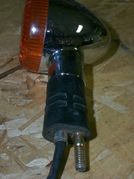
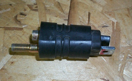
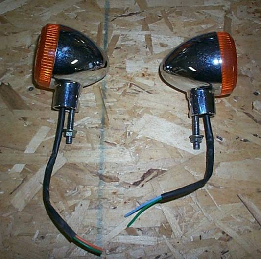
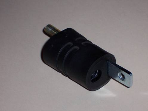
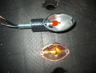
Shorten Your Turn Signals First off, I borrowed some pictures off the Magna Riders Associations: Tips and Tricks: Shorten Those Signals Web page because I lost some of my pictures (any pictures with wood in the background). OK, when you take off your signals, they will look like this (you’ll have to cut the wires to your turn signal, and make sure you cut enough to work with when you have to re connect):
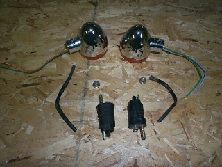
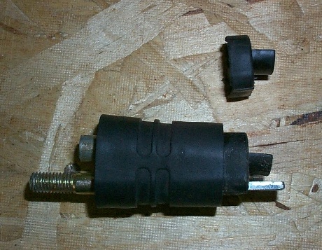
Remove the Philips screw out of the back and then take the rubber spacers out:
Then you’ll want to cut the top rubber piece that fits into the signal (the right part in the picture above). I used a simple single edge razor blade for this, worked well (save the small piece for later). Then you’ll have this:
(after you cut off the rubber top)
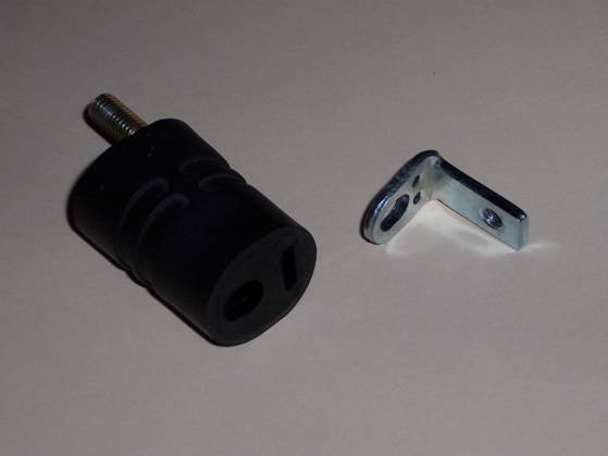
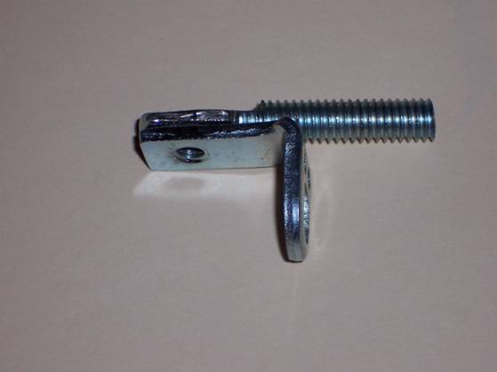
Pull out the metal tab, it should pry out fairly easily from the slot where it sticks out:
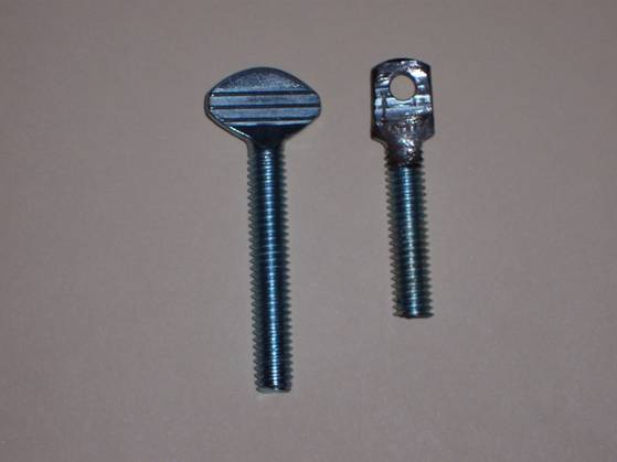
I went to True Value Hardware and got two thumb screws (5/16-18 X 2 in, 1 ½ in would work better). Then I traced the original signal tab on the thumb screw tab and ground the tab on the screw to the same shape and thickness as the original. You will need to grind up a few threads to get the thumb screw tab to fit all the way up into the signal. I also cut about ½ inch off so I don’t have to worry about the new bolt sticking out too far and hitting the rear tire if I hit a good size bump. If you got 1 ½ inch bolt that would work fine. Next I lined up the new and old tab and marked where the hole should be:
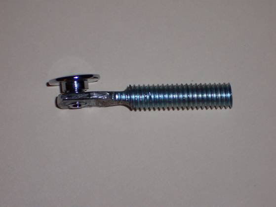
and then drilled and tapped a new hole on the thumb screw tab ( 13/64” drill bit and a 6mm-1.00 metric tap). Worked perfect.
Next I took the small rubber piece I cut off earlier put it into the turn signal, put the new tab into the slot and screwed the Philips screw. I also got new nuts to fit the new thumb screw and got some bullet connectors to hook the wires back up.
When you’re done you can slide the original tab back into the spacer and give the left over parts to someone who wants to shorten the signals the hard way. It’s really not that hard. Like I said before, I did it with a Dremel tool. If you had a grinding wheel, you could do it in 30 min.
I think it looks a whole lot better and probably the cheapest mod you can make. I think I cost me about $5…well, I guess about $15 because I had to buy the drill bit and tap, but still cheap.
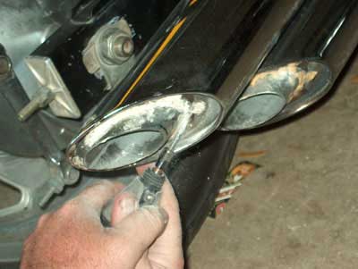
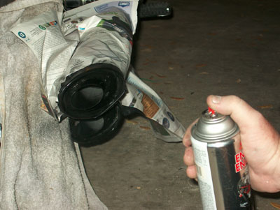
Reversing the Muffler Mod on your 3rd Gen. Magna I did the muffler mod for the Magna where you cut out the baffle part of the muffler to make the sound louder. Well, I did not like the sound and wanted the old sound back. I had thought of welding the parts back together, but did not want to take the time or spend the money to have that done. I came up with a way to do it quick and easy. I measured the length of the parts I had cut off and added the protruding length of what was left on the muffler. I bought a 3/4 X 4 ft copper tube, cut off a section as long as my measurement plus about a 1/4 inch, forced it through the protruding section of the muffler until it went into the interior muffler hole. I then traced a cut line around the outer extension, pulled the copper section out and used a grinder to trim the end to the correct size. If you have a good blade on a power saw you could cut your angle with it. I used a round file to finish off the pipe. I reinserted the copper section into the muffler, using a piece of wood and a hammer to get it back in since you no longer have a flat surface to hit against. Now you decide if you want the copper look inside the black pipe. If not, get out the black spray paint and tape off the muffler/bike area and bring back the original black look. Now you have the sweet old soft sound of the Magna back!
When Using The Poor Man's Lift When using the poor man's lift, wrap a bunge chord around the hand brake to keep the front wheel from moving as you work on the bike.
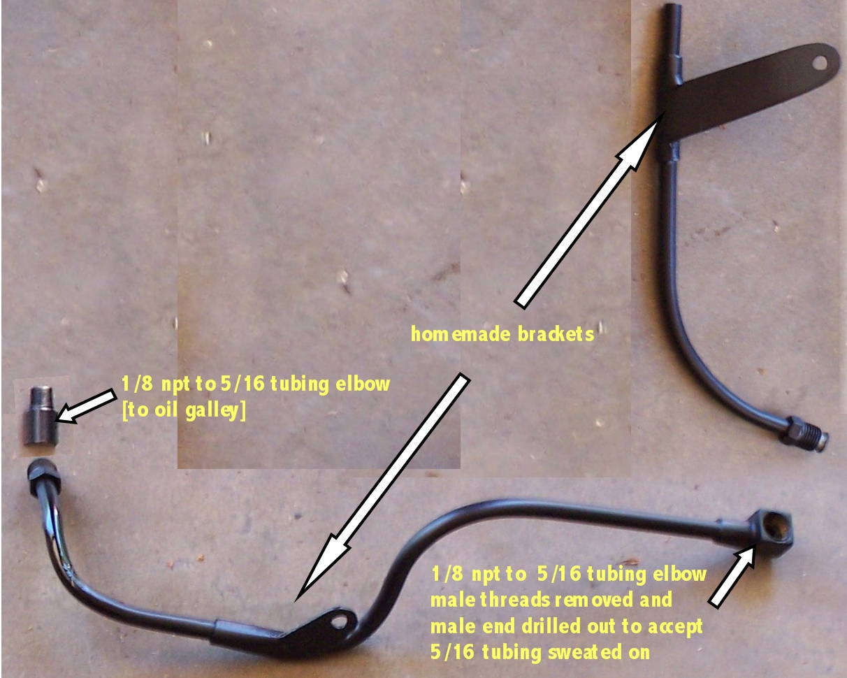
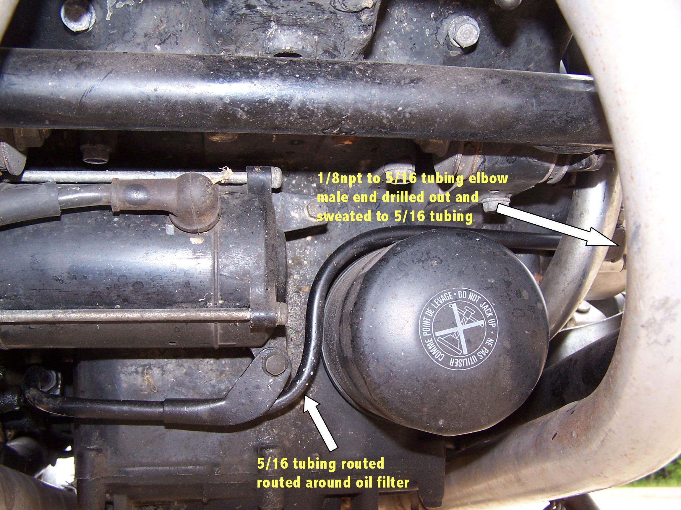
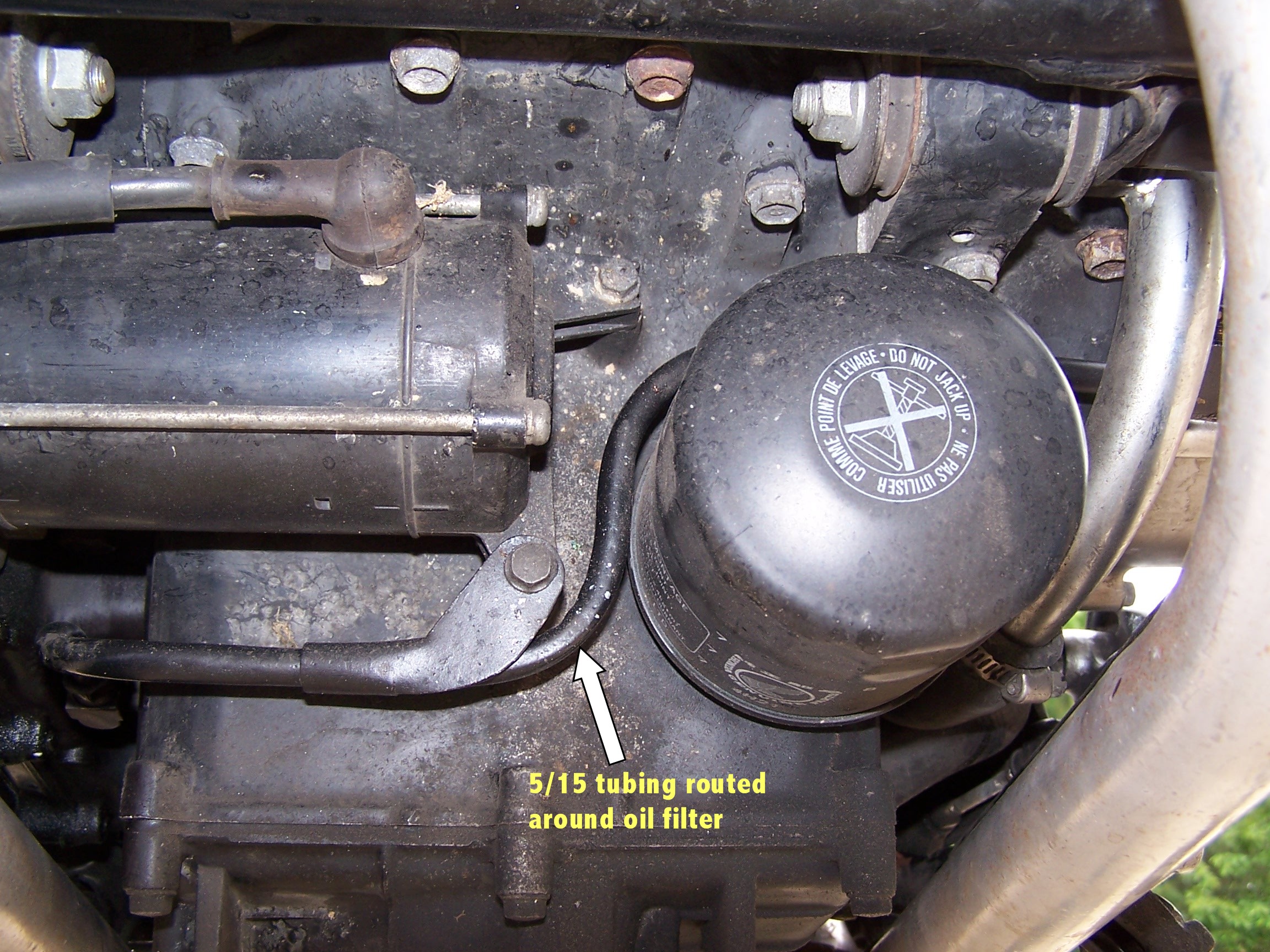
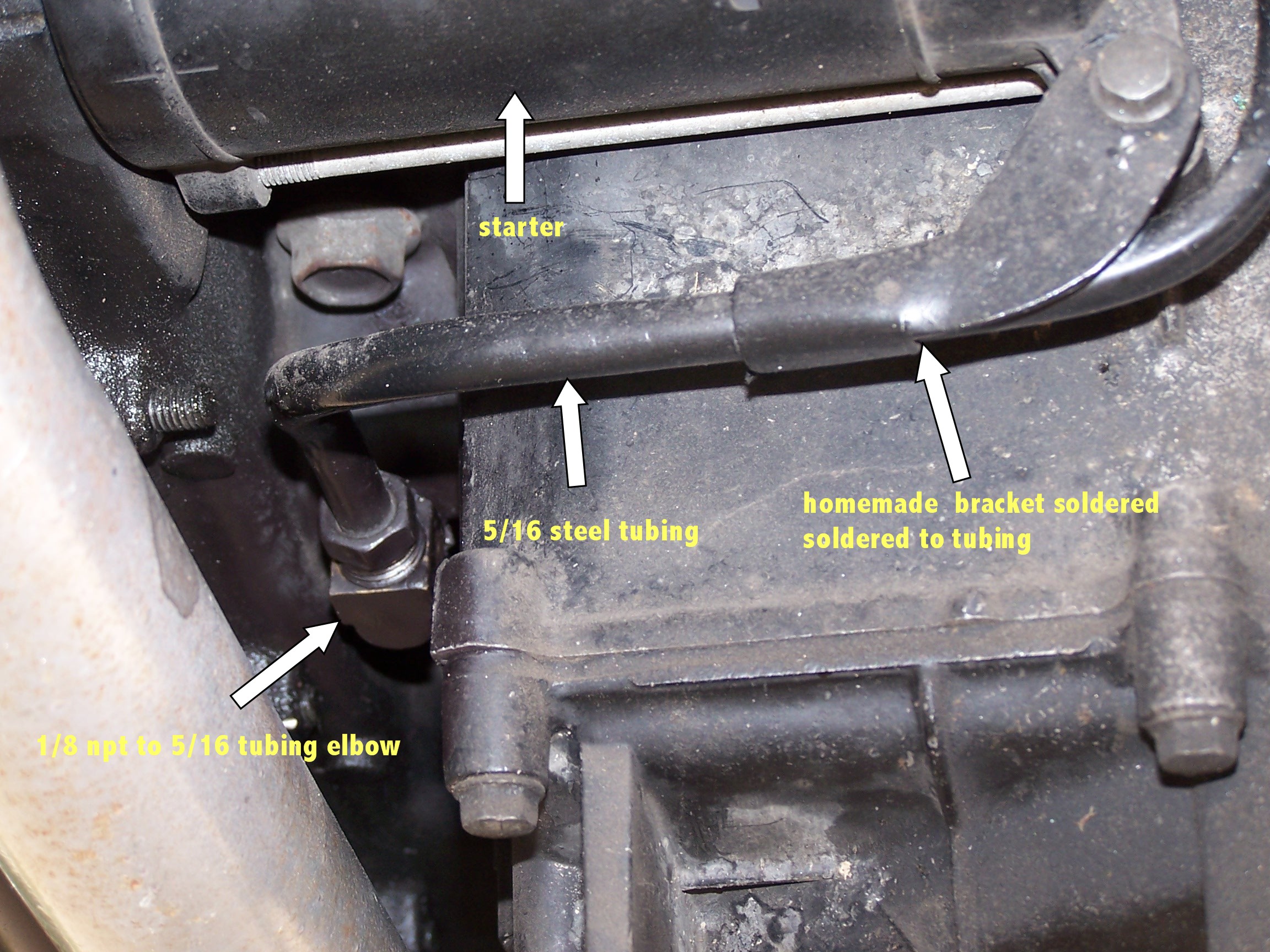
Editor note: As always, perform this modification at your own risk. Neither MOOT nor the author of this tip make any guarantees as to performance or your own results. With this in mind...do your own thing!! Here is an inexpensive oil mod I performed on my 1984 V65 Magna.
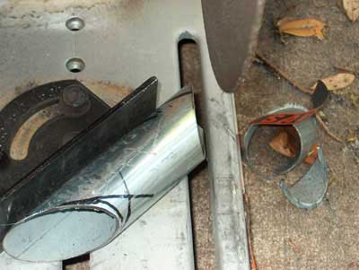
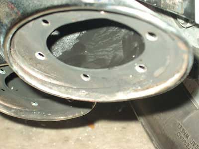
Muffler Mod Part II WARNING THIS IS A PERMANENT MOD. Having already done the other mod as described in the tips and tricks section of the Magna Owners of Texas Website. I really do not like the wimpy 1 inch pipe that protrudes from the stock pipe. First thing was to figure out what size would both look good and fit, so I drilled the rivets and measured the inside diameter of the hole that the outer plate rivets to. It measures 1 5/8th inch. This is good because Lowe's happens to have some 5ft pieces of fence tubing exactly that diameter. This tubing is as far as I can tell identical to that sold at muffler shops and Pep Boys, and no I didn't buy galvanized pipe. I have pretty much all the tools needed for this project so I did not have to buy anything. But here are the big items you will need.
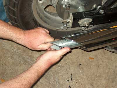
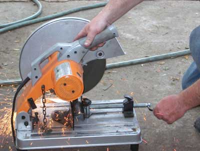
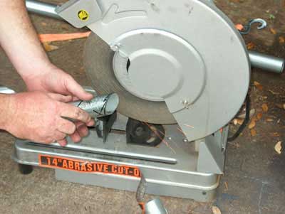
Step 1. Remove at least one of the end caps on the muffler. Be sure to drill out the rivets completely. Reach in and clean out the backside of all the rivets you just drilled out. They will make a terrible rattle if you don't. After I drilled all 4 pipes out I started the bike and blew out as much of the shards as possible then cleaned the rest out by hand. Find the angle of the factory slash cut by inserting your 1 5/8th inch tube and with a Sharpe pen trace the angle along the outer edge. This does not have to be perfect, you just want to find the angle. Your cutoff saw will do all the work for you. Step 2.
Step 3. Be sure to de-bur your tubing. and you should be wearing gloves when using these type of power tools. I will sometimes use the outside edge of the cut off saw to grind the burs off and smooth the outside edges. You will need a smaller grinder for the inside edges.
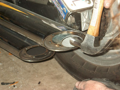
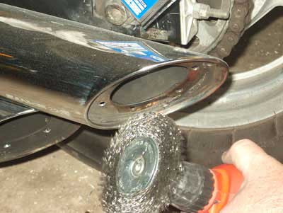
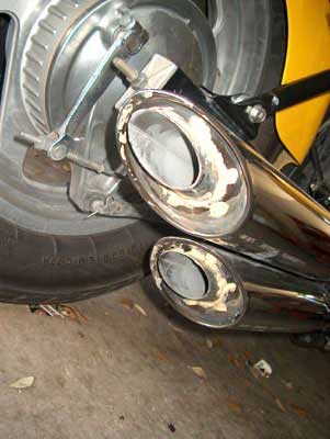
Step 4. Once you have all this done you should take a break and grab a soft drink. You will enjoy this very much. Now lets fit one of our new pipes. I had to tap the inside edge with a hammer just slightly to get it started. The factory holes are exactly 1 5/8th inch so it should be a nice tight fit. Step 5. Prep for welding. Remove your test fitted pipe. Using a wire brush you should clean the surface very well so the weld will be nice and clean. Step 6. Weld your new pipes into place. Take your time. and be very careful the new pipe is pretty thin steel and it is easy to burn a hole right through it. Step 7. Using some Muffler Seam Sealer (paste) you can fill in the rivet holes left behind. Let this set at least a couple of hours. After it sets up you can grind the hard sealer down to blend better with the pipe. Step 8. Tape off your chrome and protect your paint from over spray. Using some high temp flat black engine paint, touch up your new tail pipes. Step 9. Buy some ear plugs, this makes the bike sound much louder. Get on your bike and ride.
As usual these are the things I did to my own bike. I do not recommend you ever do anything custom to your bike. If you decide to try this mod, I can not be held responsible for any outcome either bad or good. It's your bike, you should know better. Chaz Moot #134, Central Region. 1994 Magna
Shim Install for 3rd generation Magna's
Dave Dodge carb shim install for stock mufflers or modified stock mufflers. This is only the shims not the main jet install procedure. Pull the seat and tank as usual as well as the air cleaner and housing. I pulled the auto fuel shut off diaphragm to gain access to the rear vacuum chamber covers. Remove the 3 screws holding the cover on (be very careful that you do not strip these screws as they are very soft)(This is a great time to replace these soft easily stripped phillips screws with good quality allen head cap screws, you will need 3 per carb for a total of 12. Remember the cover is plastic, do not want to break it by over tightening.), remove the diaphragm spring and diaphragm/vacuum piston containing the jet needle. Remove the jet needle holder from the piston and carefully remove the jet needle and the 1 factory installed shim. Add the Dave Dodge shim in addition to the factory installed shim, I have always just added the additional shim on top of the factory shim. Re-install the jet needle in the vacuum piston and replace the holder, make sure you fully seat the holder into the piston, it has an O-ring and needs to be fully seated. You are ready to re-install the jet needle vacuum piston assembly back into the carb, be very care to not force anything as the jet needles are very sususceptible to damage and life will be bad. They will only fit one direction and the needle has to insert into the main jet. Once piston assembly is back in place carefully fit the diaphragm back into its seat groove, you can use a very slight amount of lithium grease to hold it in place if it will not stay. Insert the spring and carefully line up the cover while seating the spring into the piston housing, it will try and bend around but gently persuade it to go straight with a small screwdriver or such. When the cover is fully seated and you are sure the diaphragm is seated and the cover fits flat and smooth replace the 3 cover screws. You are done, just have to do this 3 more times, LoL. For the front 2 carbs it will be necessary to remove the left side chrome faux air box (middle cover) and the cover stay assembly, which has 2 bolts holding it on and just slide it down and out of the way. You will have to approach both front carbs from the right side of the bike, but there is plenty of room to work. Magna Service manual chapter 5 in particular diagram 5-7, exploded view, #'s 1-7, and diagram 5-11.
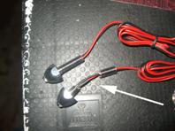
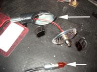
First thing you need is a new set of rear turn signals. I went with smaller profile carbon fiber look alikes. About $14.00 at cycle gear.
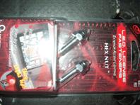
Next from AutoZone I picked up a set of lighted red license plate bolts. $6.00
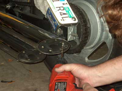
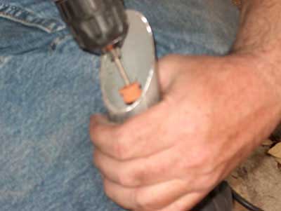
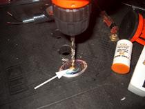
Remove the lens cap and find the center, drill a hole just big enough for the stem of your plate bolt to fit tightly.
Cut the stem of the bolt. NOTE: Be very careful, I held and turned the stem until it just started to break through, otherwise you will find yourself buying another set of plate holder bolts. DO NOT CUT THROUGH TO THE WIRE!.
Cool, now pull the wire for your fresh cut bolt stem through the hole in your lens cover and test the fit. You may need to fine tune the hole for a better fit, be sure it is tight. Thread the nut that came with plate bolt onto the short stem you have left after cutting.
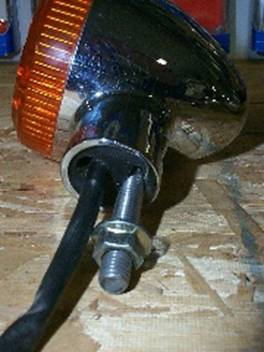
Next we pull the wires for our running lights through the bolt for the turn signal. The best way to do this is to remove the existing light and wires first, then pull your running light wires through. Now pull the turn signal wires back through, they will be tight just get them in enough to be able to reapply the lens cover. OK ready to mount on the bike. So pull all your wires back through and get your turn signal wires re-connected.
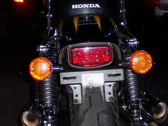
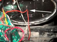
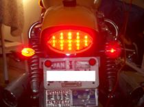
Since I replaced my taillight with a cool little cat eyed trailer hitch cover I found at Autozone a few months ago I decided to drill a small hole through the back of the new tail light, just big enough to get the 4 small wires through and make my connection there. I used silicon to reseal the small hole to keep it weather proof. Once I made the connections inside the taillight I was ready to re-assemble. Don’t forget to test everything before you put anything back together. You might find yourself tearing things apart again. So the finished product is just a little more light on the backside. It was fun and took only about three hours to do. With left blinker and brake light on
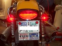
With running lights only
Chaz Moot #134
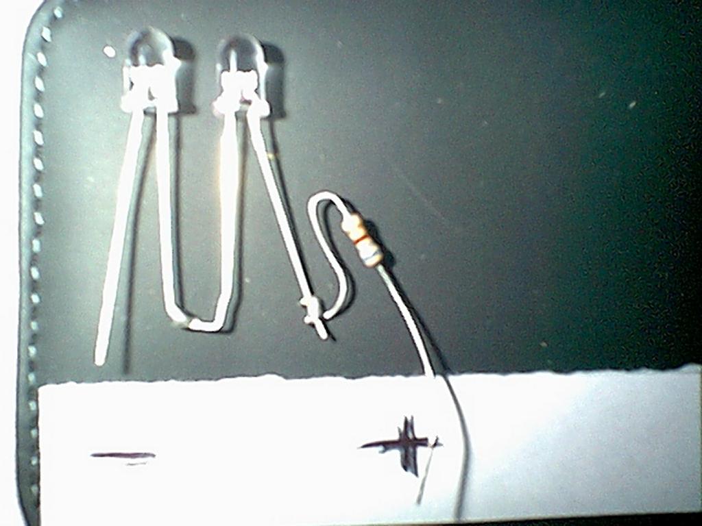
Accent Light Install Find a good electronics store in your area. Up here in Dallas we have Tanner Electronics, but Altecs will work also, I know they are in Austin and San Antonio. This is where you need to find the color bulb you want to use. The only choices I could find were amber, green, blue, and red (probably illegal). You want to be sure and pick the 'ultra bright' LED. They should have a tester there to show you the actual color and brightness of the bulbs. I used 2 bulbs at each light station, 2 bulbs require 1- 680 ohm resistor. I put a fuse (7-10 amp fuse will work) between the battery and the line, and a switch next in line. With this kind of set up you need + and - feed for the whole line. Also, get some duct tape, electrical tape, heavy duty two sided tape, nylon ties, a good solder gun, rosin core solder, and about 3 feet of stranded speaker wire. For each light station do the following: each LED has a long (+) and short (-) leg coming out of it; solder the resistor ( it is common on both sides) to the (+) side of the LED, the (-) of the LED to the other bulb's (+) side, keeping the bulb heads even; solder the resistors other edge to a (+) 2" long piece of speaker wire, and then solder the (-) end of the LED to a 2" piece of (-) speaker wire; place the unit over a piece of duct tape long enough to double over the other side to cover all exposed metal up to the bottom edge of the bulb heads; this completes the assembly of one light station. Run the positive speaker wire from the (+) side of the battery post to the fuse assembly, the other end of the fuse assembly to the switch, then attach the wire to the other side of the switch. Connect the (-) side of the wire to the (-) battery post. Run the wire (+) & (-) to the first light station, solder the negative side of the light station to the negative speaker wire, the plus side to the plus speaker wire. You must tap off of the main line at each station, do not run it in series! Do this for each light station. The end of the speaker wire is taped (not together!) Try to use the nylon tie to secure the light station to the bike. We took the tank off and placed the light stations on the frame when possible, if not, use the two sided tape to secure it to a well cleaned surface.
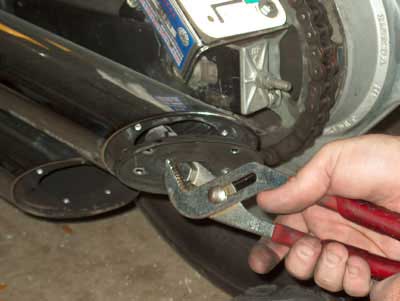
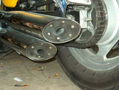
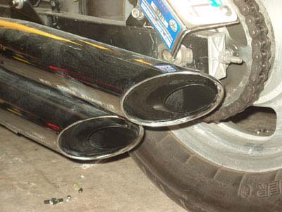
by Greg Cothern (MOOT #1) and Robert Hilliard on 2/1/2003: First we use an Awl or anything similar to knock out the center pin in the rivets holding the back plates to the muffler housing. This leaves the outer rivet still in place, you must remove it as well. To keep from damaging or enlarging the mounting tabs installed in the housing, we did not drill out the outer rivets. We instead used our Awl in a circular motion, using pretty good force to "whaler" out the remaining portion of the rivet. A pair of needle nose pliers and Wire Dykes help a lot here as well. Remember these rivets are just aluminum, and the mounting tabs are steel, use enough pressure to work through the aluminum. Then once all rivets are removed, you will need 2 medium to large size vise grips. Placing one on the exhaust tube that protrudes from the muffler. Clamp the second pair perpendicular to the exhaust tube on the first pair of vise grips. The second pair is to give you something to hit with a hammer (you knew a hammer was needed on your expensive stock mufflers to perform this mod, didn�t you?, heheheh). Strike the second pair of vise grips with a good amount of force, may take a couple attempts to dislodge the end plate and baffle from the muffler. This is a good time to take something like a small magnet to retrieve the rivet pieces that have fallen inside the muffler. Once the end plate has been removed take it to a vise, where you will clamp the baffle tube very tight. With a good hacksaw cut the baffle tube on the end plate side leaving a small portion of tube. Once you have cut the baffle off, use a file and wire brush to remove any burrs or flaking coatings. It is now time to reinstall the end plate using 3/16" X 1/4" long rivets to attach the end plate back to the muffler. Clean thoroughly with solvent or alcohol etc, then mask things off and spray paint with flat black or semi-gloss black paint. High temp paint is not needed but if you feel compelled to do so, go ahead. One last tip, only remove one end plate at a time as to not get them mixed up, and they can be put back on the correct muffler. Then when all is finished, fire up your beloved Magna and listen to the new music she makes, and realize that for only a couple of dollars in paint and rivets you have a sweet sounding exhaust system, that will not ring your bell while riding on long trips. This muffler mod has been performed on Greg Cothern's bike and Robert Hilliard's bike with great success. The sound it creates is not as loud as say, Vance & Hines or Cobra pipes, but it'll give your Magna a throatier, slightly louder sound that you will definately notice for a fraction of the cost. Feel free to contact Greg Cothern or Robert Hilliard for more information or listen to their bikes at the next MOOTMAG. 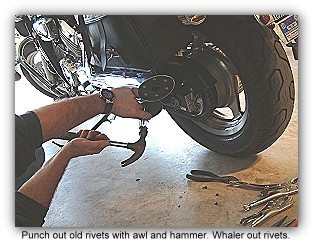 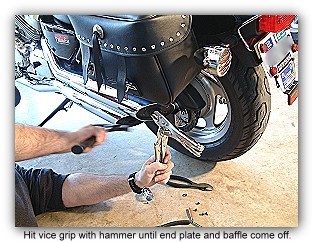 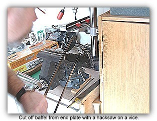 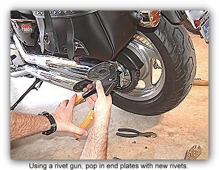 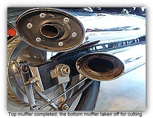 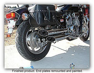 Note: In cutting the baffle away from the end piece, cut the pipe just an inch or two from the end piece as illustrated in the two pictures below.  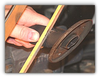 sent in by Arvid Hagen, Bergen, Norway on 01/18/2003:  Put yourself on the bike and position it upright in the riding position in front of a wall. Have another person measure the distance from the center of the headlamp to the surface of the road. Measure off 6m from the front of the lamp and draw a horizontal line same height as the center of the lamp on the wall. Put yourself on the bike and position it upright in the riding position in front of a wall. Have another person measure the distance from the center of the headlamp to the surface of the road. Measure off 6m from the front of the lamp and draw a horizontal line same height as the center of the lamp on the wall.Turn your lights on and put them on high beam. While your weight is still on the bike adjust the light vertical so the light is even above and below the horizontal line you drew on the wall. Then adjust the light horizontal so you have an equal amount of light to the left and right of the center point. This puts your high and low beam almost perfect. sent in by J. Reviere, MOOT #156 on 01/24/2003: Synchronizing the carbs does require either a set of mercury manometers (most accurate method) or a set of high quality vacuum gages. Also, a pair of hands that are very small with fingers about 6" long that bend in all directions would be highly useful.  No, the synch adjustments aren't "difficult" to get at... Not at all.
Since it's necessary to have the tank removed, or at least suspended
to access the carbs, you need a small aux tank with hose to supply fuel
because to do the job, the engine must be running.
No, the synch adjustments aren't "difficult" to get at... Not at all.
Since it's necessary to have the tank removed, or at least suspended
to access the carbs, you need a small aux tank with hose to supply fuel
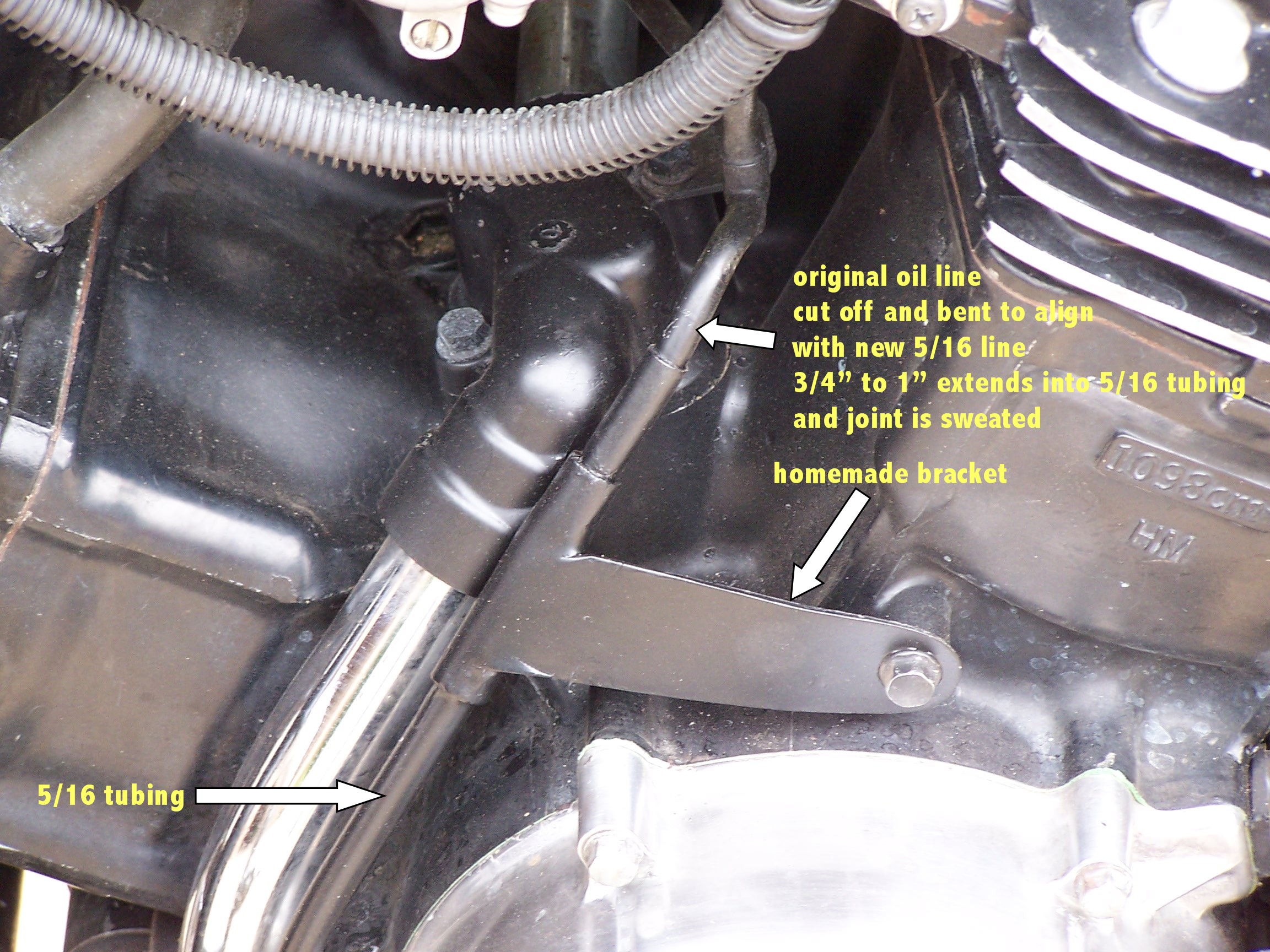
because to do the job, the engine must be running.Here's my method for "tuning" the idle mixtures: The optimum idle mixture setting is best achieved with an exhaust gas analyzer connected to the engine running at normal operating temp. The next best process for doing this is to "tune" each carb with a very accurate and very sensitive tachometer (the factory tach on most bikes is NOT sensitive enough for doing a good job) attached to the engine using what is called the "lean roll-off" method. As you lean the mixture very very slowly a wee bit at a time, eventually you will come to a point at which the engine RPM rises slightly for a brief time. That point is "lean roll-off". Once you find the "lean roll-off" for a given carb (they aren't all the same) then you back the idle mix screw out about 1/4 of a turn for best idle setting. This process effects ONLY the idle mixture, it does not effect synchronization of the carbs. That's a whole another pack of dogs. Turning the idle mix screws left (counter clockwise) makes the mixture richer. Turn to the right (clockwise) to lean the mixture. WARNING: These screws are soft metal. DO NOT bottom them forcefully. If you do you will distort them and ruin their fuel metering capacity. From: Robert Gray The Valkyrie(Vk) tank comes in two sizes Interstate and Regular Size. The Interstate is too big. The regular tank after conversion gives 6.3 US gallons. The length of the reg. Vk tank is the same length as the stock Magna tank: that was the big plus - you bend off the ring brace on the front end of the Vk tank and it is a perfect fit so far as length is concerned. The underside takes some modification. In fact that is where ALL of the modification takes place. I cut out the bottom side of the Magna tank and cut out the bottom side of the Vk tank and put the Magna bottom on the Vk bottom side. Then I added strips of metal - welding them in to fill in all the gaps because the width of the Vk is of course wider than the Magna. This is where you gain your volume. Take care to keep the underside "centered" we welded new half circle brackets on the new underside (the half circle brackets that fit on the rubber mounts on the frame of the Magna) because the old brackets (on the Magna tank) did not fit in the same location on the larger tank. Weld the half circles at the same height on each side left and right so the tank remains level. Venting the tank: Two ways. You can use the Honda venting system and transfer that into the Vk tank or you can use a vented gas cap. I made a vented gas cap out of the existing Vk cap by drilling an 1/8" hole on the bottom side of the gas cap. Do not just push the drill bit all the way through you will ruin the lock and the spring - drill slowly down to the springs within the gas cap locking mechaniesm and stop! That is approx. a depth of maybe 1/2". I used the petcock from the Magna and moved the mounting threads over about 1/2" from the left side of the tank (left as you sit on the bike) don't get too close to the side, that large nut on the petcock has to have room to turn and seat firmly. So the threads are welded in place about as far back to you (as you sit in the seat) and close to the edge. So if you draw an oval it would be in the lower-right edge - of course on the underneath side ! In reality you do not have to use the Magna petcock you could use any petcock that fit even some that are on HD's ! OH, shocking! I had the inside of the tank bathed in that stuff that creates a bladder - called creaming your tank - then I had the tank painted. One more thing - you will need new risers - I got mine from the guy on the Magna site # 765 Dobie Gillum they are perfect for the job and they look good too. From: Kirk Allen "After trying epoxy alone twice on a broken tab, I tried the following and the tab hasn't broken since. First, I thoroughly cleaned all the old epoxy off the base and the tab. Then I used the point of a 3-cornered file to roughen the hollow area under the tab. I used Loctite #82565, 'Plastix Advanced Plastic Bonder,' to attach the tab. This product is a Super Glue type glue with an 'activator' that you brush on the edges to be joined immediately before applying the glue. Then I filled the hollow area under the tab with epoxy putty; I don't recall the brand but JB Weld or any similar product should work." From: Brad Phillips From: Robert Hilliard I went to my local auto parts store and purchased several 1/8" and 3/16" fittings along with a "T" and some nylon 1/8" line. All was easy to install, but when I got down to mounting the gauge itself, that took me some time and ingenuity to complete. There is not much to mount anything to on the right side of the engine. So, I found a piece of high-impact plastic that just happened to be shaped the way I needed it for the mounting. Well, I did do a little modification. 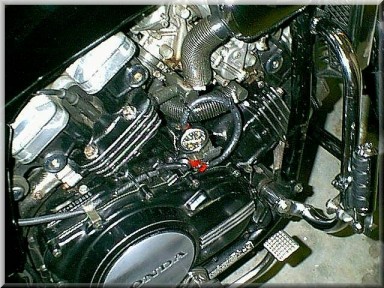
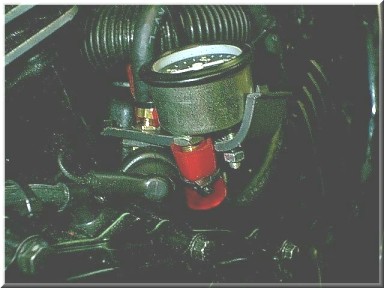 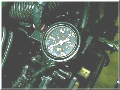
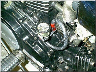 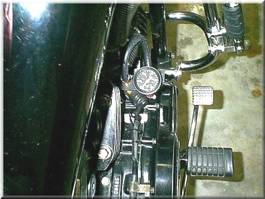
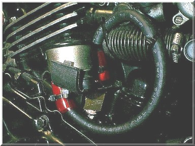 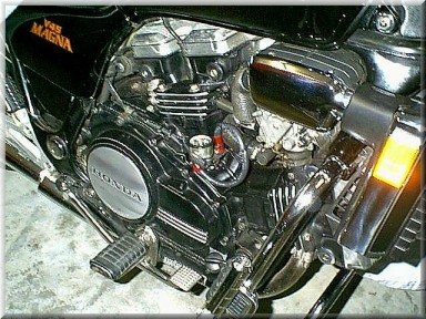 I took the old sending unit off and mounted the "T" to the block. Then I screwed in the old oil sending unit and hooked it up. Then, off the top of the "T", I screwed in the oil line to the gauge. By the way, I applied teflon tape to all the connections. I cut a piece of rubber gas line to the same length as the oil line and ran the oil line through the gas line for added protection. I braced the line with several tie wraps and viola, it's done. After taking several test rides with high RPM, I am happy to report there were no drips. Even though the 1/8" nylon oil line seems rather vulnerable to leakage, I have read that someone used the same nylon line for over 20,000 miles on their V-4 with no problems, so...we'll see. Mav idles at about 15-20psi oil pressure at cold startup. It lowers to about 10psi after warmup. At 5000 to 6000 RPM, the gauge reads 80-85psi. From: Dave in Massachusetts 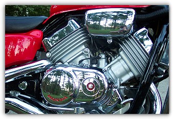 On the '94 and up Magna's (and perhaps the older ones), there is the Honda name on each side of engine casing (just behind the stock footpegs). Take some model paint with a small brush and paint the logo any color you want. Then, after it dries a little, wipe off the excess paint on the letters with a rag and rubbing alcohol, using your fingernail. The paint will harden and not heat up and run off. I also painted the inner part of the oil casing bolt on the right side too. On the '94 and up Magna's (and perhaps the older ones), there is the Honda name on each side of engine casing (just behind the stock footpegs). Take some model paint with a small brush and paint the logo any color you want. Then, after it dries a little, wipe off the excess paint on the letters with a rag and rubbing alcohol, using your fingernail. The paint will harden and not heat up and run off. I also painted the inner part of the oil casing bolt on the right side too.
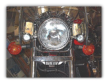
From: Moose  From: Greg Cothern, MOOT #1 I have a large National Cycle windshield on my Magna so it dictated that I use the smaller lights, if you do not have a windshield then you can take advantage of the larger lights if so desired. To mount the light bar I loosened the headlight mount from the lower triple tree and slide the light bar underneath, tightened the mount back down, and that is it the light bar is installed. Next I installed the lights to the light bar with the included hardware. I did not want to cut into the stock wire harness so I made a wire harness with switch, fuse link, and connectors and put in a wire loom to protect the harness. Attached harness directly to the positive post on the battery (the lights ground to the light bar which in turn grounds to the triple tree by contact) and followed the stock wiring harness along the frame and found a location for the switch to be mounted. They provide great light, not all that expensive (ebay is a good source for the parts if you can find them from time to time), and is unobtrusive. Here are some pics for reference. 
 From: Greg Cothern, MOOT #1 Start by placing the bike on a sturdy lift making sure to strap securely, safety is always a priority! Remove front wheel, drain fork oil from tubes, the drain plug on '96 and later is located at the bottom of the fork tube up through where the axle was residing. On earlier models the plugs are visible on the side of the lower forks. Make sure you get all the fluid out, may require you to gently move the lower fork sliders up through the suspension travel. Be careful and do this very easy as you can upset the bike on the lift. Re-install your drain plugs at this time making sure you clean your parts for re-installation. Remove fork tube caps, remember they are aluminum and deform easily, caps removed, gently raise lower fork legs and the stock metal spacer, washer, and spring will reveal itself to be easily retrieved. These are the only 3 items you need to remove from inside the fork tubes. Now you're ready to drop in the new springs from Progressive, does not matter which direction you place them into the forks, just make sure you put then in the same. Re-insert washer that came out with stock configuration, but do not put stock metal spacer back. It is replaced with a piece of 1" PVC pipe cut to a length of 5.12" for stock height (94-03), or can be shortened to lower front, but be aware if you lower front an inch you will need to lower the rear to keep the proper suspension geometry. Make sure you clean the PVC thoroughly with denatured alcohol or such as to not introduce contaminants into the inner workings of your forks. Now you must replace the fork oil with your favorite brand, 10wt is stock, if you prefer a little more dampening then use 15wt fork oil. It is completely acceptable to mix weights to create custom weight oil if you want something different. Such as half 10wt and half 15wt to get 12.5wt, your choice. I would not go lower than 10wt personally. Refill the tubes with fresh fork oil, Progressive Springs instructions states a maximum level of 5.5" measured from the top of the fork tube to the top of the oil with the forks compressed without springs or spacers installed. You can make a simple dipstick for this. You can also cut your stock metal spacer is you like to the length but easier to use PVC. Now your ready to reinstall the fork caps, these can be a little tricky, best method I have found is to have someone help. I use a 1/2" drive socket and long extension, lightly seat the cap have your helper hold downward pressure, hand start the cap on hand tight this should prevent stripping the threads. Once hand tight you can tighten with ratchet to specified torque rating in your manual.
3rd generation Magna or your Super Magna From: Greg Cothern, MOOT #1 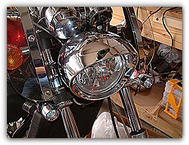 Order the following from www.ronayersmotorsports.com or www.partsfish.com for a 02 VTX 1800C: Order the following from www.ronayersmotorsports.com or www.partsfish.com for a 02 VTX 1800C:Headlight unit - 33120-mch-671 x 1 rubber cover - 33180-mr7-003 x 1 headlight case - 61301-mch-670 x 1 headlight rim - 61302-mch-670 x 1 headlight stay a - 61312-mch-670 x 1 special screw (5mm) - 90104-kz3-b00 x 2 screw (5x9.5) - 90380-ge2-760 x 3 This is a straight forward process, assemble the light and bolt on. Fits the stock headlight mount and plugs in to the factory headlight wire harness. On the Super Magna it may be necessary to ever so slightly bend the instrument cluster upwards so it is not in contact with the VTX headlight bucket. From: Dave in Massachusetts From: Biff Van Cleve, MOOT #135 Shifter Adjustment 1994-up Honda Magna V750 (One Way) Note: I'll
begin by saying there may be more ways than this to adjust the shifter,
but it worked well for me and it's not rocket science so that helps.
I had my bike for two weeks when I decided to do this bit of surgery.
Click below for the document explaining the procedure and supporting
documents. From: B. J. Fazio, MOOT #75
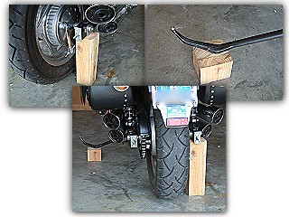
Take a 4"x4" piece of wood and cut a piece 11.25 inches long and another piece 2.75 inches long. To use, all you do is place the 11.25 inch piece between the floor and under the right back swing arm. (Please see pictures at left). Get on the left side of your Magna and gently push the bike to the right. Once high enough, slide the 2.75 inch piece under your kick stand. Ease your bike down and voila! That's all there is to it. To let your bike down, reverse the process. Once on the lift, you'll
find your bike is very stable to where you can clean or wax that
chain or clean your back rim. Your back tire rotates freely.
From: Robert Hilliard  There are a myriad of things you can spray into your helmet to make it smell better, but here's something you can do that is easy, safe and will keep your helmet smelling fresh all the time. There are a myriad of things you can spray into your helmet to make it smell better, but here's something you can do that is easy, safe and will keep your helmet smelling fresh all the time.Fabric softener sheets...You know, those little sheets your wife puts in the dryer to help your clothes to be soft and smell fresh. One brand is called Bounce. Just take a couple of sheets straight out of the box and place them inside your helmet while it's being stored. When you ride, take them out and when you store your helmet, put them in. It's that simple. Your helmet will smell fresh all the time.
by Biff Van Cleve (MOOT #135):  Fork Seal Replacement Documentation
 Fork Seal Replacement Acrobat Reader Version Fork Seal Replacement Acrobat Reader Version
Master Cylinder Assembly Tips (Vintage Magna) by Jeff Heard (MOOT #103): Here is what to do..... 1) Bleed the clutch/brake line like normal. 2) Put a box end wrench on the banjo fitting, break loose the fitting, and just reclose it. 3) While moveing the clutch lever in, crack loose the fitting and reclose it close to the end of travel. Have a rag over the fitting connection that you are working on because it will spit at you as pressure expells the air and a little fluid. Do not release pressure on the lever till the fitting is tightened back up or you will suck air back into the line. 4) Continue this until only fluid is being pushed out.
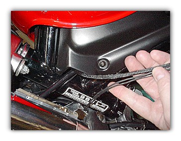
by N.J. Rockwell: 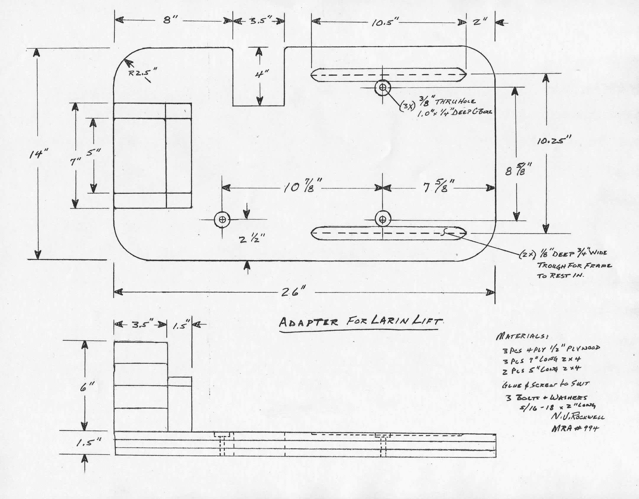
Notes: The adapter is solid and works great. It is simple enough to build, strong, and when mounted on the lift, rolls right under with the bike resting on it's sidestand. I have a larger, heavier 170/80 Dunlop rear tire and a Cycle-istic break stay rod, but it looks like there would still be plenty of room to roll it under a bike with a stock 150/80 tire. The concept and function of this adapter comes from a picture MadMax had posted elsewhere some time ago (imitation-flattery intended). It functions by creating a 3-surface offset plane with support up under the swingarm brace in front of the rear tire and support at the two frame rails under the motor. My version of the adapter is constructed of 3 layers of �" plywood with a block of 2x4s on one end. There is a cutout in the back edge to clear the sidestand, two shallow troughs spaced to fit the frame rails and 3 holes to bolt the adapter to the lift. 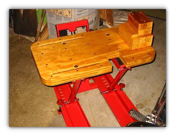
Key to making it solid so it will not flex under the bike's weight, I think, is the use of copious amounts of wood glue, clamps and screws; I put the 1�" screws in from the top and bottom spaced about every 6 inches and let it dry overnight. Used 2�" screws & glue with the block of 2x4s, the (2) 5" pcs. on top of (2) 7" pcs. and (1) 7" pc. on the front for stability. To route in the two 1-ply deep troughs, I used a Dremmel with a small sanding drum, took just a few minutes. The bolt pattern on my Larin Lift may or may not be identical to one you have, so I'd suggest drilling small pilot holes, inverting the adapter and lift and confirm the pilot holes are centered in the bolt holes. To prevent the heads of the Allen bolts from hitting the frame rails, I counter-bored a 1" diameter hole �" below the top surface to contain the washer and bolt head. Sawed a coffee can size radius on the corners to allow the lift stabilizer arms to swing out clear. Attached the 2x4 block with 3" screws up thru the plywood. Block sanded the edges. Finally, sprayed the adapter with several coats of spar urethane to make clean up easier. Paint would also work. I snug the adapter to the lift with the bolts just to make placement under the bike more consistent; in back, make sure the break stay rod bolt is not sitting on the 2x4 block and that the far side rail is positioned to go into the trough. The bike is balanced well enough raised on the lift that I can sit on it without tie downs, but you can bet I'll use tie downs every time I start wrenching on the bike. 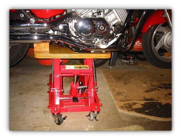
Standard disclaimer: I build it, I use it; you build it, you use it at your own risk. N.J. Rockwell
Feel free to type it in and submit it below. Considerable care has been taken in preparing information and materials which is displayed on this page. However, the MOOT Membership, MOOT Leadership and MOOT Webmaster is unable to provide any warranty or guarantee concerning the accuracy or completeness of any information contained herein. All Information contained on this page has been submitted by the listed author(s). The listed authors, MOOT Members, MOOT Leadership and MOOT Webmaster assume no responsibility or liability for any injury, loss or damage incurred as a result of any use or reliance upon the information and material contained within this web page. | ||||||||||
| |
||||||||||


 Have you ever
needed to just lift the back of a newer Magna without spending a
lot of money? Maybe you need to clean your back rim or clean and
wax your chain? Well, now you can perform those chores with minimal
fuss by using the Poor Man's Lift. Here's how you make one:
Have you ever
needed to just lift the back of a newer Magna without spending a
lot of money? Maybe you need to clean your back rim or clean and
wax your chain? Well, now you can perform those chores with minimal
fuss by using the Poor Man's Lift. Here's how you make one: